
ArkButton: A Wireless Split Keyboard, Printed and Soldered by Hand
58 keys, two nRF52840s, ZMK, and one thumb position deliberately left empty. Notes from building a wireless split keyboard, including the clock bug that killed the right half and the tenting plate that only printed once it stood upright.
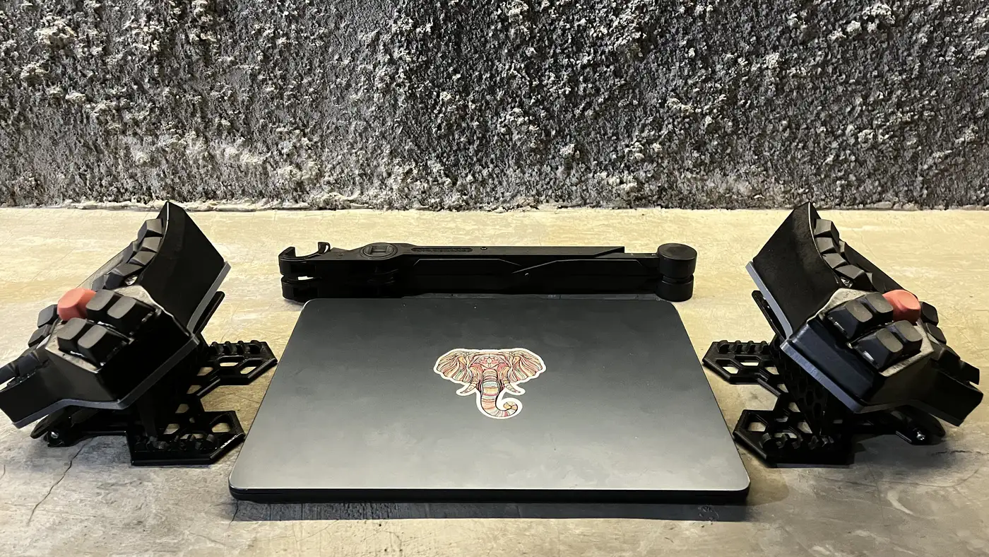
The keyboard I type on now is called ArkButton. Scylla/Charybdis geometry from Bastard Keyboards, printed on an Elegoo Neptune 4 Pro, soldered direct with no hotswap sockets, running wireless on ZMK across two HwThinker Pro Micro nRF52840s.
My favourite thing about the project isn’t the hardware. When I open the ZMK keymap, the first line of the comment header reads:
ArkButton, keymap direplika dari Dactyl Manuform 4x6 milik Aris (ArkButton, keymap replicated from Aris’s Dactyl Manuform 4x6)
The previous board, the Dactyl Manuform, has been retired for a while. Different case, different microcontroller, firmware moved from QMK to ZMK, the TRRS cable gone and replaced by Bluetooth. What didn’t change is where the keys are. The layout survived; the hardware got replaced. My fingers didn’t have to learn anything again.
Specification
| Geometry | Bastard Keyboards Scylla / Charybdis |
| Key count | 24 finger + 5 thumb per hand = 58 |
| Controllers | 2× HwThinker Pro Micro nRF52840 (nice!nano v2 compatible) |
| Firmware | ZMK, in its own repo: charybdis-wireless-zmk |
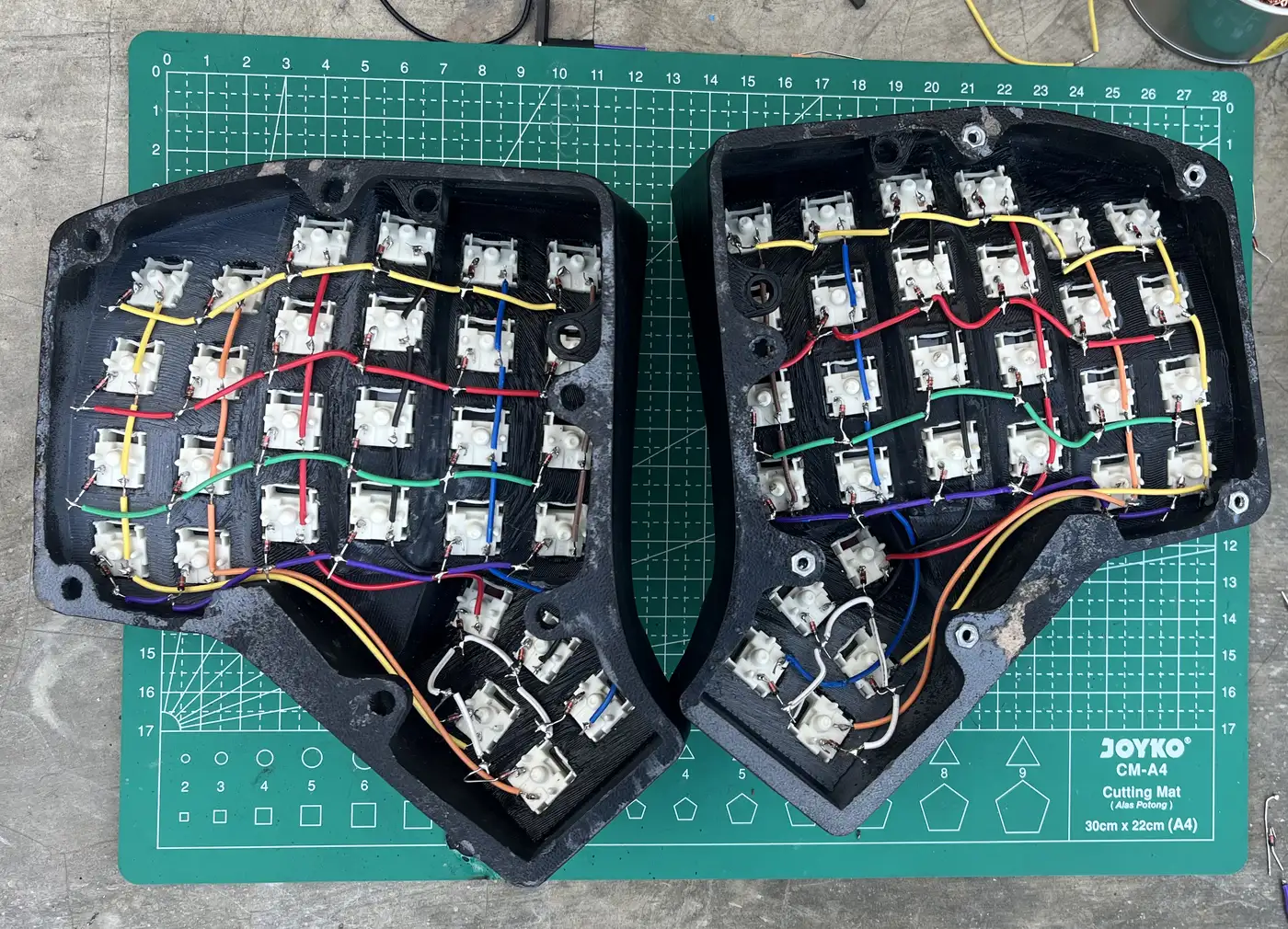
| Matrix | col2row, one 1N4148 diode per key, 29 per hand |
| Link | BLE, left is central, right is peripheral |
| Assembly | soldered direct, no hotswap |
| Printer | Elegoo Neptune 4 Pro |
| Stand | articulated tenting stand, OpenSCAD sources in tools/tent/ |
The key that isn’t there
The thumb row has six matrix positions but only five switches. The innermost position on each hand is left unpopulated, not forgotten, deliberately not fitted. My thumb doesn’t reach it comfortably, and forcing in a key that would only ever be pressed by accident is worse than having no key at all.
The position stays in the keymap as a phantom:
// THUMB kiri: SHIFT MO1 GUI SPACE ALT (Del*) | THUMB kanan: (Bksp*) BSPC ENTER HOME MO2 SHIFT
//                                     (* = inner column, no switch)
The bindings are still written so every row keeps its 12 columns. Deleting them would make everyone editing the file (me, six months from now, included) miscount.
Why Esc is on the pinky and Ctrl sits under it
The finger rows top to bottom: numbers, Tab, Esc, LCtrl. On an ordinary keyboard that third position is Caps Lock and the fourth is Shift. Here Esc sits on the left home row, one pinky away from A, with Control directly beneath it.
The reason is nvim. Leaving insert mode is a motion I make thousands of times a day; if it needs a pinky stretch to the top-left corner, that’s thousands of stretches. Shift moved down to the thumb, which is a far more sensible home for a key that gets held rather than tapped.
The tmux prefix lives under my right thumb
This is the part that usually needs explaining twice. In dotfiles/tmux/tmux.conf:
unbind C-b
set-option -g prefix Home
And in the ArkButton keymap, Home is the fourth key of the right thumb cluster. So every tmux command (switch window, split a pane, all of it) begins with one thumb press. No Ctrl gymnastics anywhere.
Home was already in the old Dactyl keymap (KC_HOME, on the bottom right row). When the thumb cluster grew to five keys it simply moved onto the thumb, and that’s where it finally made sense.
Four layers, one of them born from going wireless
- 0: Base. QWERTY plus a number row.
- 1: Numpad. Held with
MO1on the left thumb. - 2: Nav. Held with
MO2on the right thumb. - 3: Adjust / Bluetooth. Appears on its own when layers 1 and 2 are held together.
Layers 1 and 2 are near-exact copies of the Dactyl keymap, numpad in the same places, arrows on the same A S D F. Layer 3 has no counterpart at all on the old board, for a plain reason: the old board had a cable. The moment it went wireless there had to be somewhere to put BT_SEL 0–4, BT_CLR and sys_reset. That layer wasn’t designed; a hardware decision forced it into existence.
conditional_layers {
    tri_adjust { if-layers = <1 2>; then-layer = <3>; };
};
The bug that killed the right half
This one took the longest.
With everything soldered and flashed, the left half worked perfectly as central. The right one didn’t. It wasn’t dead either, flashed as a standalone central it ran fine. Only the split link failed, and the log repeated itself: Security failed err 9, then a disconnect with reason 0x08, over and over.
I suspected the pins, the wiring, the bonding. None of them. The cause: these HwThinker clones have no 32.768 kHz crystal, which the nice_nano_v2 board profile assumes. Without it the BLE low-frequency clock drifts, and the tightly-timed split link runs out of time mid-security. The fix is one line:
CONFIG_CLOCK_CONTROL_NRF_K32SRC_RC=y
CONFIG_CLOCK_CONTROL_NRF_K32SRC_XTAL=n
There was a second one of the same family. The central has to hold one peripheral (the right half) plus five Bluetooth profiles for five hosts. The default is five connections, one short, and the one left without a slot was always the right half:
CONFIG_BT_MAX_CONN=6
CONFIG_BT_MAX_PAIRED=6
And one pin trap: P0.22 is dead as a GPIO on this board because QSPI flash claims it. Col1 moved to P0.31.
Mirroring is a firmware problem, not a soldering one
The right PCB is a mirror of the left, so wiring both hands with the same pins in the same order comes out with the right hand’s columns reversed. The first instinct is to tear it down and rewire. Don’t. charybdis_handwired_right.overlay reverses its col-gpios order and adds col-offset = <6>, exactly the way ZMK’s own corne_right.overlay does. The keymap is still written left-to-right in the visual order your eyes see.
Why solder direct
The priority was durability. Gateron hotswap sockets went into the shopping list and were cancelled before payment: the switches are Gateron G Pro rated around 50 million clicks, so the odds of me swapping a switch on this board are close to zero, while sockets add one contact point per key that can loosen or oxidise over the years. A diode and enamelled wire soldered permanently is far less that can fail.
The tenting plate has to print standing up
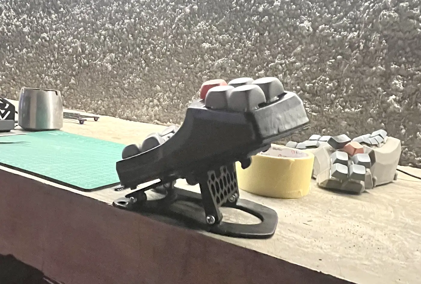
The most stubborn mechanical part was the tenting plate. Roughly ten failures in one session, every one printed flat, and every time, the hinge knuckles, which are thin tall tabs in that orientation, curled and nested into each other somewhere around layer four or five.
The funny part: I had tried the vertical orientation earlier and crossed it out myself with the note “rejected, tippy”, a 138 mm-tall wall on a 14 mm footprint does look impossible. It turned out to be the answer, and the original designer’s readme had said “print them vertically” the whole time. Standing up, the hinge knuckles stop being overhanging tabs and become gussets against a vertical wall. The unexpected bonus: that thin footprint lands dead centre on the bed, far from the warped corners.
The second problem that session had nothing to do with geometry: Z0 drifts every time the printer homes, by around ±0.15 mm within a single session. Any offset injected into the gcode is wrong the moment the printer re-homes at the start of a print. The fix is to home once, verify true zero with the paper test, then strip the G28 line out of the gcode so the print reuses that verified home. And the rule I wrote out in capitals for myself: re-glue the bed, redo the paper test. Glue thickness alone shifts Z0 by 0.1 mm.
One last trap, from a note dated 30 June: the upstream repo’s file names are handed backwards. The file called ..._plate_right.stl is actually the left plate. That only surfaced after comparing renders and scoring the outline IoU against the case. Every row in the print queue ended up rewritten by the hand it actually is, not by the file name.
This repo stores no output at all
.stl, .3mf, .gcode, .uf2 and every render PNG stay out of git. Only sources go in: OpenSCAD, scripts, notes. All of it rebuilds:
tools/fetch-upstream.sh          # clone upstream at pinned commits
node tools/cycle.mjs <target>    # build → validate → capture → summary
There are three three.js viewers for looking at the result without opening CAD, preview-keymap.html, preview-tenting.html and preview-wiring.html. The last one is the one I had open most while soldering.
Firmware isn’t stored as a file either. GitHub Actions in the ZMK repo builds the .uf2; the artifact gets downloaded, unzipped into firmware/, then:
firmware/flash left      # or right, or reset
firmware/kbstatus        # Bluetooth state on macOS
flash reset is the safety net: it writes settings_reset to both halves to clear stale BLE bonds. Any time the two hands suddenly refuse to recognise each other, that’s step one.
What’s still unfinished
The board is in daily use, including for writing this. Both halves now sit on their tenting stands. The battery holder and the cradle mount to the case are deliberately postponed until everything else is actually bolted together.